Simple Circuits
Simple Circuit

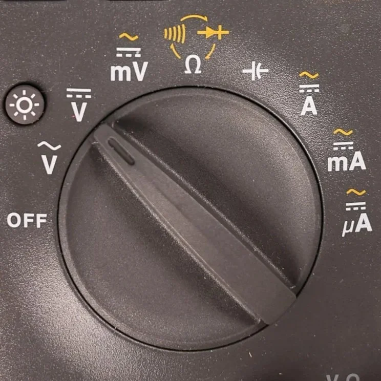
Meter set to DC Volts
The Microtrainer uses a 3V Battery that is stepped up to 5V DC.
Look for the DC voltage symbol on the meter:
A solid line stacked above dashed lines.Rotate the dial to Volts DC

Turn the Master Switch On
Slide the MASTER switch to the ON position (right)

Ohm’s Law
Displays the formula V = A × R with triangle or wheel diagram for easy reference.
Includes example calculations for voltage, current, and resistance.
Reinforces the mathematical link between the quantities students measure on the front.
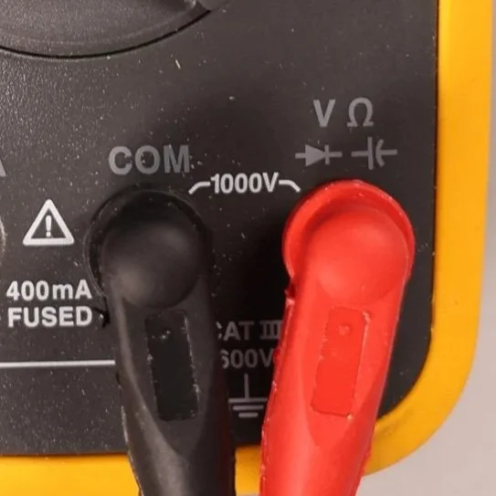
Meter Leads
Black lead → COM (Common)
Red lead → V (Voltage)
Once these are in place, you’re ready to start measuring.
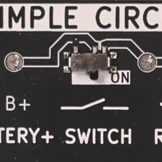
Turn on the Simple Circuit
Slide the Simple Circuit Switch to the ON position (right)

Basic Meter Tips
Quick reference for correct meter setup:
Voltage: probes across a component; circuit powered on.
Resistance: across a component; circuit unpowered.
Current: meter placed in series; circuit powered.
Reminds students to verify meter mode and lead position before every test.
Understanding Voltage in a Circuit
This lesson walks through how to measure voltage in a simple circuit using the Microtrainer Series & Parallel Card. Students will see how voltage appears at different points in the circuit, how components affect voltage levels, and why voltage drop testing is an essential diagnostic skill in automotive electrical systems.
Learning Goals
By the end of this lesson, students should be able to:
Identify DC vs. AC voltage settings on a multimeter
Properly place meter leads when measuring voltage
Understand the concept of potential difference
Measure source voltage (battery voltage)
Measure voltage before and after a switch, resistor, and LED
Perform voltage drop tests across individual components
Interpret voltage changes to understand how the circuit is functioning
Required Tools & Equipment
Microtrainer Series & Parallel Circuit Card
Digital multimeter (Fluke 15B+ or similar)
2. Turning on the Microtrainer
Turn the master switch ON.
Turn the simple circuit switch ON to power the LED.
The LED should now illuminate, showing the circuit is active.
3. What You’re Actually Measuring: Potential Difference
Voltage is always measured between two points.
When you measure voltage, you’re seeing how much electrical pressure exists from one point to another.
The most common starting point is from Battery Positive to Ground.
4. Source Voltage Measurement (Battery Simulation)
Place your leads like this:
Red → Battery Positive (B+)
Black → Ground (GND)
On the Microtrainer, this should read about 5 volts, which simulates a vehicle’s 12.6 volts on a healthy battery.
This measurement evaluates the battery’s ability to provide energy for the rest of the circuit.
5. Measuring After the Switch
Now check the voltage on the output side of the switch.
Keep black on Ground
Move red to the right side of the switch
You should see very close to 5 volts, showing that the switch is providing full system voltage when closed.
To check for differences between the switch input and output, measure between them:
Red → Before the switch
Black → After the switch
This will show very little voltage, meaning the switch has no significant resistance.
6. Voltage Before and After the Resistor
Before the resistor
Voltage will still be near 5 volts.
After the resistor
Expected reading is around 1.8–2.0 volts.
This drop occurs because the resistor and LED share the remaining voltage.
7. Performing a Voltage Drop Test
Voltage drop testing shows how much voltage is used by a specific component.
Across the Resistor
Red → Before the resistor
Black → After the resistor
Expected drop: About 3 volts
Across the LED
Red → Before the LED
Black → After the LED
Expected drop: About 1.8 volts
The resistor and LED together use the entire 5 volts before the circuit reaches ground.
This follows the principle:
All of the source voltage must be dropped across the components before the current returns to ground.
8. Understanding the Complete Voltage Path
Starting at 5V source:
Switch: ~0V drop
Resistor: ~3V drop
LED: ~2V drop
Back to ground: 0V
The total drop equals the source voltage.
This is how technicians verify circuit health and diagnose issues such as excessive resistance, poor grounds, and failing components.